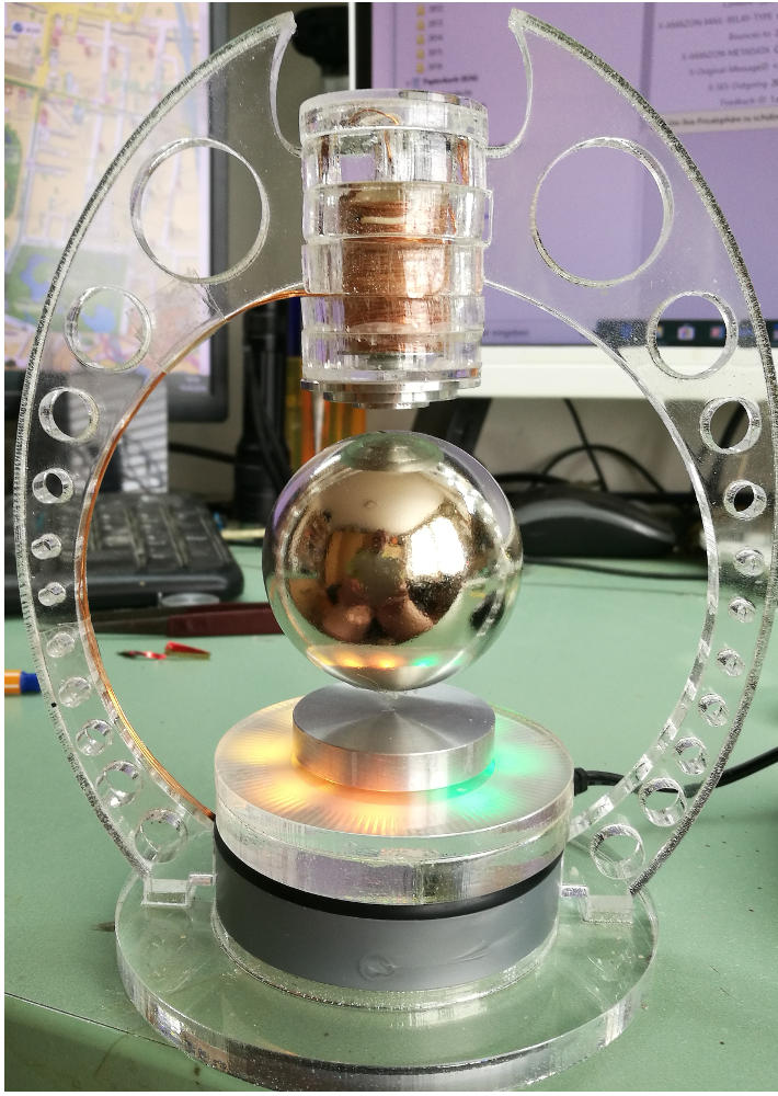
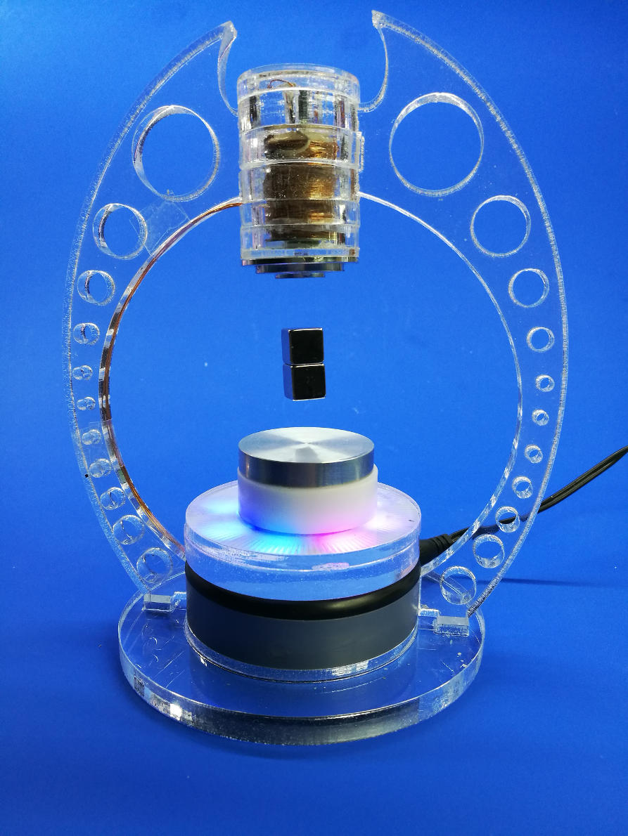
Magnetic Levitation (1 inch gap, stable, low cost)
I’ve managed a simple solution for the magnetic challenge in order to get a stable levitation. After several experiments and a lot of research I came up with a solution using a handful components, more particularly, only five electronic parts were needed: a power supply, an Arduino, a handmade coil, a MOSFET and a hall-sensor. With a small piece of software running on the Arduino, the magnetic cubes can be hold in a very stable position. But wait, it isn’t so easy, I’ve got several issues and finally run into a serious problem, but finally I’ve got the solution…
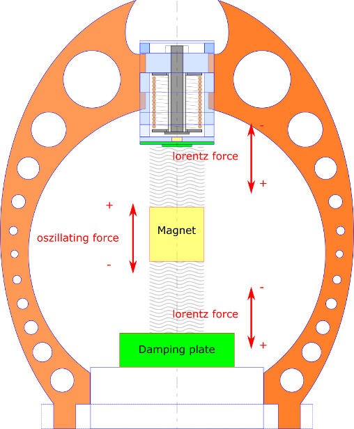
Lets start with the big picture: an electromagnet with a coil and an iron core on top attracts a floating magnet, a hall sensor reads the magnetic strength in the gap between the two magnets. An electronic switch turns the coil OFF if the strength exceeds a certain value (threshold) and turns it ON if the strength falls blow this threshold. The threshold is exactly the line, where the sum of the up-pointing forces are in balance with the gravity of the floating magnet. The target is to keep the magnet very close to this line.

So what’s the main problem trying to keep a magnet in a constant position from the electromagnet? Stability is the answer. In the configuration above, there are some facts that stability can’t be reached even if the electromagnet is switched with a perfect timing and high frequency, after some seconds or minutes the system tends to oscillate. Several articles on the WEB are describing this situation and most of them are recommending a PID controller. Well, to cut a long story short, I had no success with PID controllers, neither software-based nor hardware-based. But even if I had been successful, setting the PID-constants would be for one specific configuration only and I like a more general system, where I chan change the type/size/weight of the magnets without reconfiguring the software. Here you can see the cubes getting out of control:
And finally here is my solution to fix this problem: using a damping plate/disc does the magic job. Putting a non magnetic, good electric conductor, such as aluminium or copper on top and/or bottom of your system will eliminate the oscillating due the lorentz force, which is generated by the induced current in the conductor and acts against the oscillating force.
 :
:
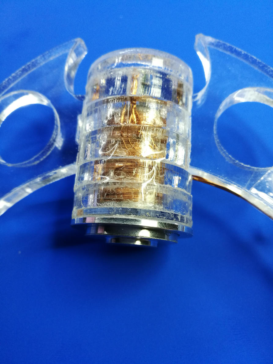
However, to achieve a good damping factor, the plate/disc must not be too far away from the magnet, it also depends how strong the magnet is. For my strong N42 cubes I’m using an aluminium disc with 6mm thickness, 40 mm of diameter and a distance of approx. 15mm to the magnets bottom, which is sufficient enough (the damping disc is at the lower section of the picture):
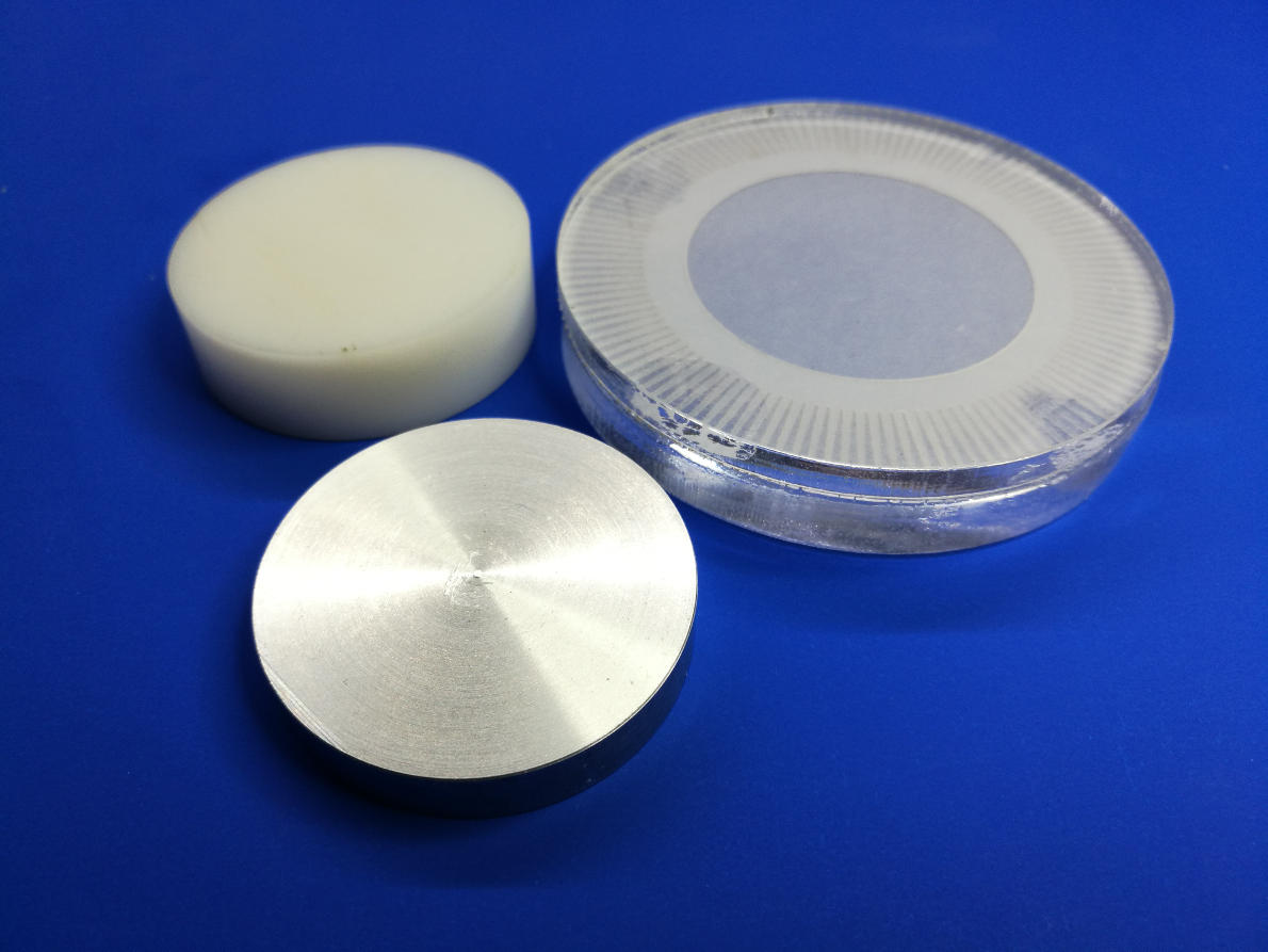
If the damping plate is too far away from the magnet, spacers can be used (non magnetic material such as plastic, acryl etc.). Good candidates for damping plates are also CPU heat sinks.
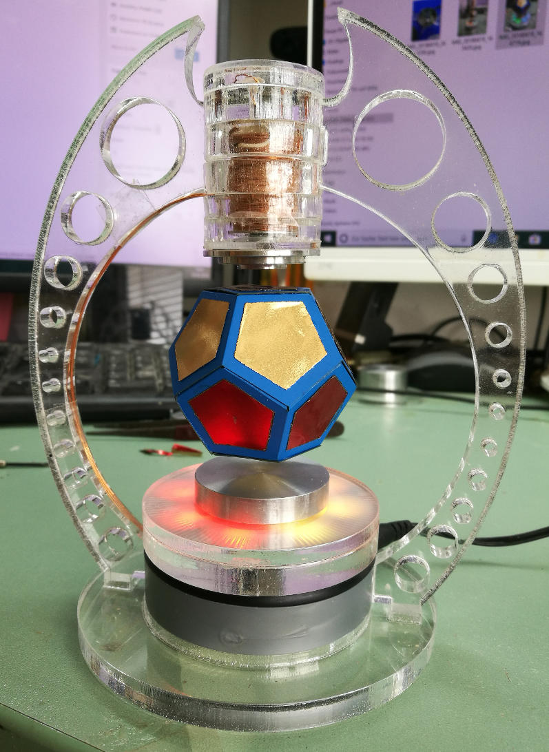
For my levitation system I can change magnets with different style, strength and size on the fly without reconfiguring the software. Sometimes, depending on the magnets, I have to remove/add a spacer, but this can be done without effort.
For people interested on how I built up the systen, here is some technical Information:
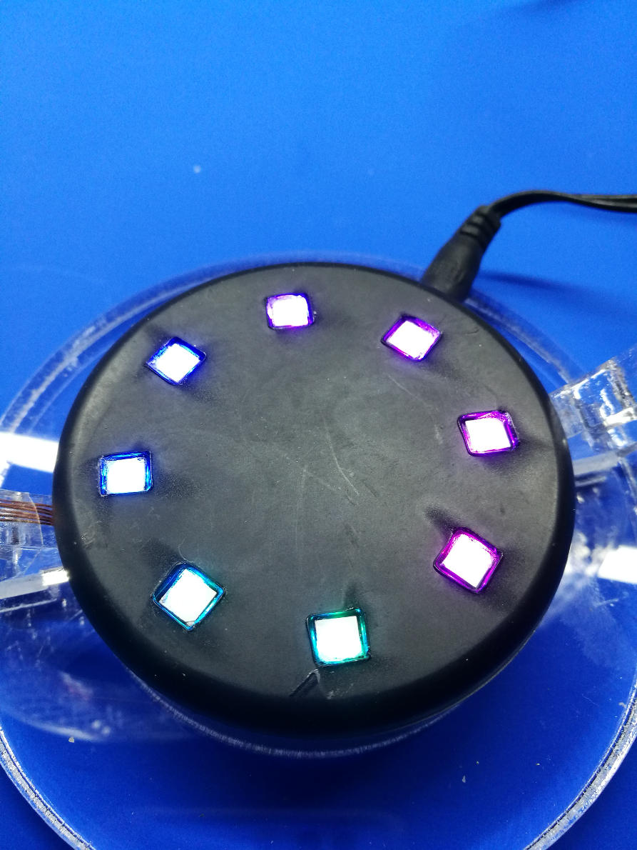
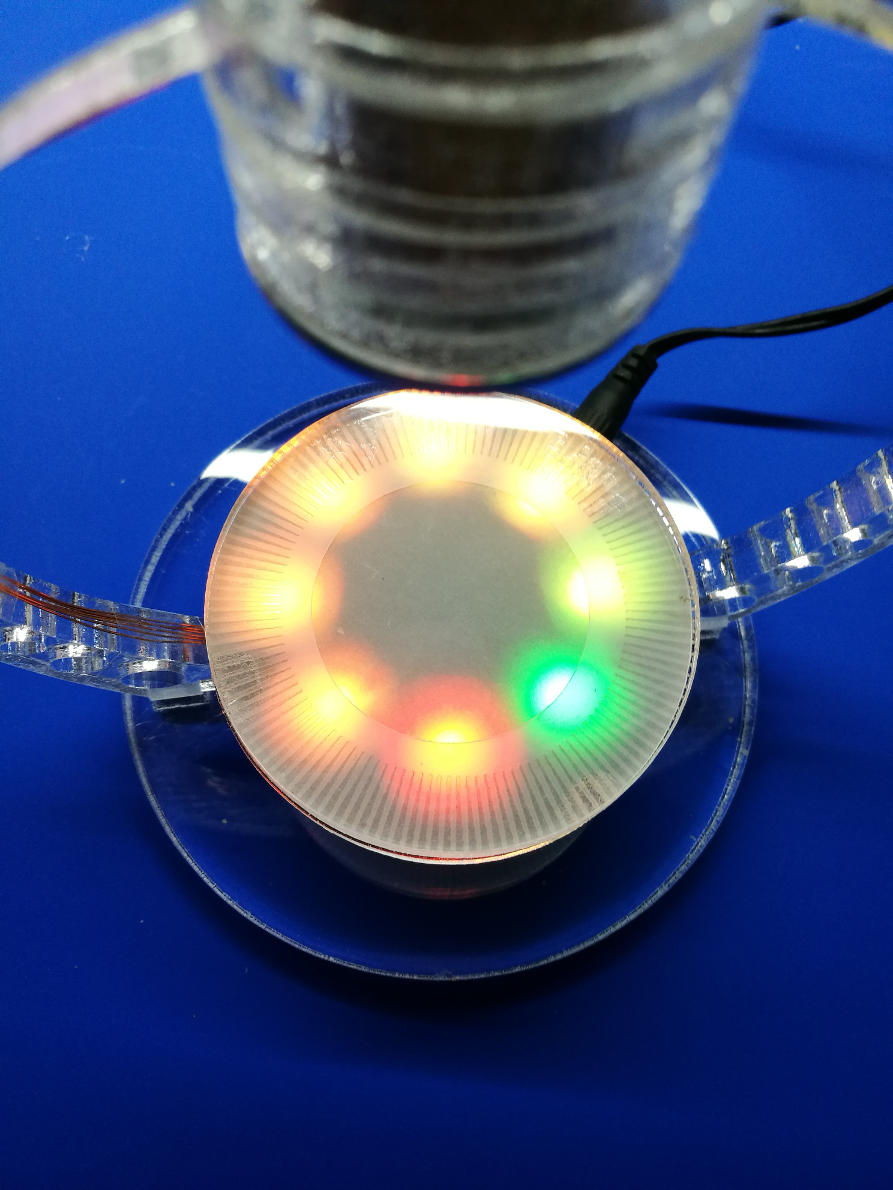
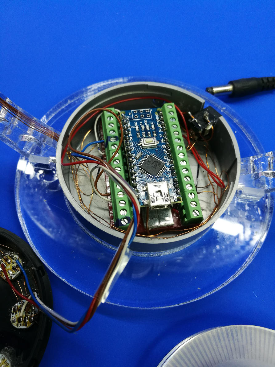
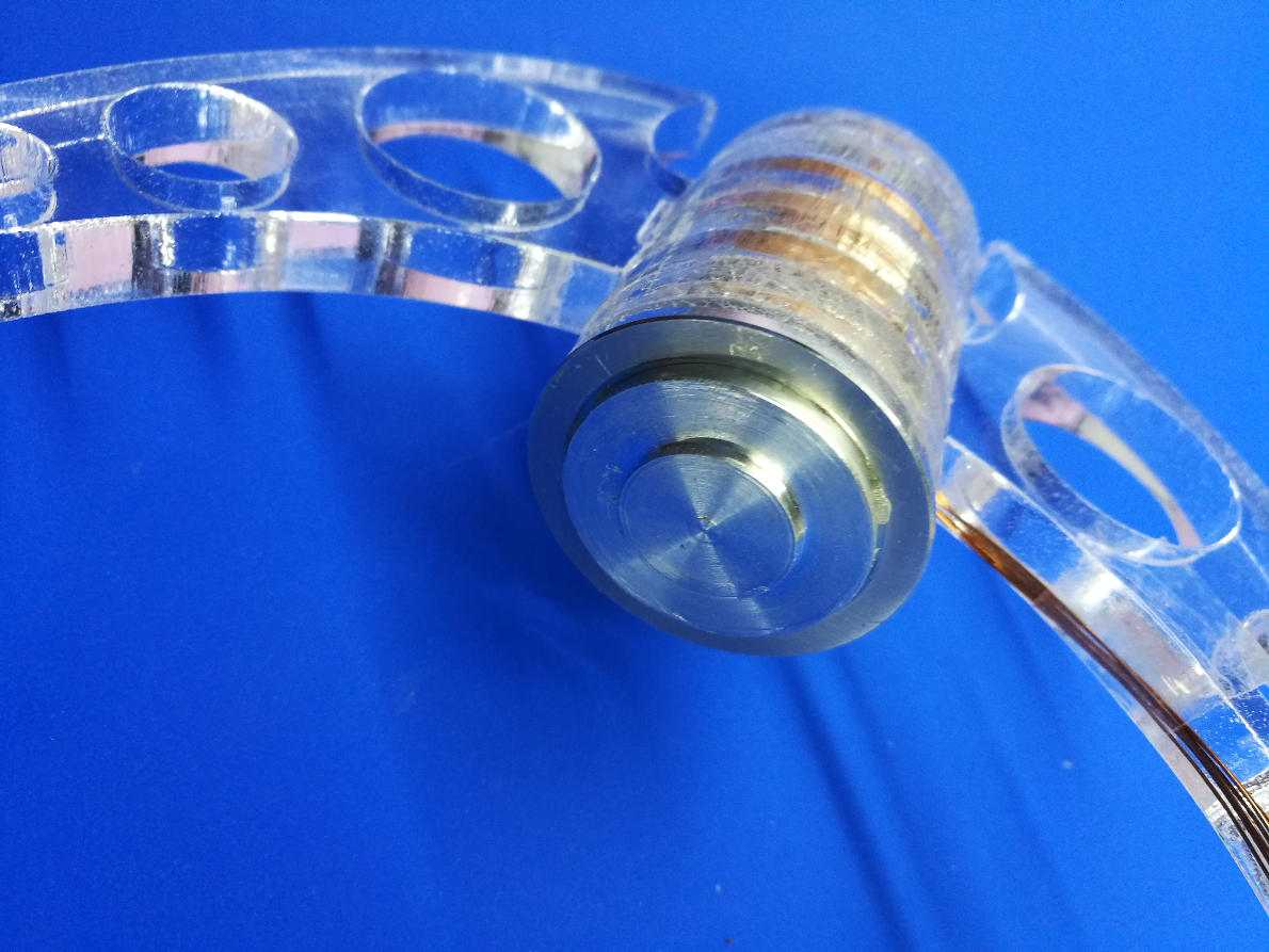
The system is supplied with a 7.5V power supply and draws a current of 40-50mA to hold the magnets (< 400 mW). The power supply is connected to the Arduino-nano Vin-pin and also to one end of the coil. The coil is not very critical, I used a 0.3mm wire and filled up the windings from 7 to 20 mm diameter. The coil length is 20 mm and the resistance is about 30 ohms. The other connection of the coil goes to the drain of a N-channel power MOSFET (5N50 ), the gate of the MOSFET is connected directly to an Arduino output and the source is connected to the ground. For the magnetic sensor I’m using a Hall-Effect chip from Allegro (A1302), the output signal goes directly to an analog input of the Arduino. The 5V supply for the A1302 is coming from the Arduino pin. For optical effects I’m driving some Superleds (Apa102), but this is optional and has nothing to do with the core system.
The software is using the Arduino AD-Converter in free running mode and makes the decision whether to switch the coil ON or OFF after each conversion is completed. So the main loop, which acts as a simple PW-Modulation, is very straight forward:
#define THRESHOLD 622
#define OUTOFRANGE THRESHOLD-50
void loop() {
  unsigned int sensorValue = analogNext();
  if (sensorValue >= THRESHOLD|| sensorValue < OUTOFRANGE) {
    digitalWriteD(OUT_PIN, 0);
  }
  else {
    digitalWriteD(OUT_PIN, 1);
  }
}
To determine the threshold value, just leave the coil unmagnetized (comment the if/else block) and insert a serial.println(sensorValue) statement instead. Now, while watching the values, put manually the magnet below the coil until you feel some force pulling upwards. The monitored value is now a good starting point for your threshold. In the example above the threshold value is set to 622 which can be tuned by approx. +- 10-20 digits to compensate different magnet weights. The OUTOFRANGE constant is used to switch the coil OFF if no magnet is present and thus to reduce the power consumption on idle time. The value isn’t that critical, I decided to set this constant 50 digits below the threshold.
The whole sketch can be downloaded from here.
Other projects
Useful components:
Arduino Mini, Nano, Mega, laser 405nm
RaspberryPI I, II
WLan ESP8266
and much more.
")


